
Rockler Workbench
While I’m fortunate to have a good-sized workshop in the two-car portion of our three-car garage, I have to be very mindful of the amount of floor space the tools, carts, and stands occupy. With the ever-present annual threat of hurricanes, I have to be able to rearrange things in a moment’s notice to fit both vehicles into the garage (see Garage Tetris for more on this topic).
Everything is on wheels, with the exception of the miter saw station. With that being said, there is barely enough room in the back of the shop to squeeze all of the current tools and cabinets. I’d like to free up a little bit of floor space if I can, but not get rid of any of the tools that I currently own. Of all of the shop stands currently in the shop, the only candidates available are the drill press stand and the flip-top tool cart, which houses my planer and belt sander. All three tools are used a bit infrequently, so getting them off of the floor is probably a good idea anyway.
What’s Not to Like?
I built my latest version of a workbench/assembly table, Workbench Version 3, almost two years ago. It’s design was based on Johnny Brooke’s T-Track Table. It was originally positioned directly behind my table saw to act as my outfeed table as well as an assembly table. My shop went through a couple of layout changes over the ensuing two years, and the original design of the workbench began to show some limitations.

Here you can see the workbench as the outfeed table to the table saw, before I changed the layout around (the first time).
For starters, the back side of the workbench, which was originally facing the back of the table saw, had almost no area for clamping (it was just the 3/4” hardwood trim). There was the open area between the end cabinets which DID allow for clamping, but that was still limiting.
Secondly, the t-track installed on the top just was not used as much as I had anticipated. Maybe, in the future, I would utilize this type of feature more often, but at the moment it’s a pain in the ass more than anything. Next, I decided to apply laminate to the top of the workbench to offer some durability and make cleanup easier in the event of glue squeeze-out, but the laminate’s performance wasn’t as good as I’d hoped it to be. Finally, the top did not turn out as flat as I wanted. There is a definite crown in the middle of it, making it difficult to assemble large pieces. No amount of screws and/or shims would level the top. All of this necessitated a new workbench design.
Are You Flipping Kidding Me?
The more I thought about it, the more I liked the idea of the planer and the belt sander being stored under the workbench on a set of drawer slides. This would get them off the floor and out of the way and still make them readily accessible when needed. The drill press, on the other hand, could not be put into a drawer. It is simply too tall for that application.
The old location of the drill press, on the end of the miter saw station, was actually an ideal spot. Other than having to slide it forward when needed and back when not, it was a great place to store such a cumbersome and top-heavy tool. I just needed to come up with a way of setting it up in such a way as to not need moving while still leaving the top of the miter saw station fully accessible (more on that in the Rockler Miter Saw Station article).
During my search for a solution to all of my problems, I remembered a series of videos that Jason Bent did in redesigning his new workshop. Jason went away from making all of his major shop cabinets from the ground up and opted to utilize multiple sets of Rockler customizable shop stands instead. For his workbench, he went with two 48” x 48” shop stands to make one large 48” x 96” table. I liked that idea, so I started to play around with it a bit.
***NOTE: Rockler has since done a redesign of their customizable shop stands and made some improvements (one being addressing the sagging issue with the longer stretchers). The new stands can be found here.
I didn’t have room for a 48” wide table, so I made mine 36” instead. Having two 48” x 48” tables wasn’t really going to work for me either. I checked Rockler’s website and they offered a 60” option for the work stand stretchers. Those, coupled with a set of 36” stretchers would give me the 96” I’m looking for. On the 60” side I could house both the planer AND the belt sander. But, how would I deploy them when needed?
I still liked the basic premise of the flip-top tool stand, but would something like that be possible in a drawer? I started to model things up in Sketchup and played around with the dimensions of the flipping platform. I was using the flip-top design devised by Drew Fisher at Fisher’s Shop. It could only rotate in one direction and it was easier to lock into place with one sash lock.
Getting the platform to flip was not the problem now. I just needed to devise a way to structure the sides so that I could attach drawer slides to them. A regular set of drawer slides would NOT be strong enough to hold the weight of the planer, at nearly 100 lbs. Top that off with the weight of something like an 8Q x 6’ x 10” hickory board, and there would be A LOT more weight on those slides. And, on top of all of that, it would be ideal to have the slides lock in place when deployed to ensure no problems when using the tools.
I had good luck with CabinetParts.com in the past, as they have a large array of options available for drawer slides. Based on the measurements of the top and its overhang, and the dimensions of the sander and planer, I would need a 24” set for the sander and a 32” set for the planer. I selected all of the criteria needed and I was left with a couple of options. Heavy duty slides in those measurements supported 450 lbs, well above what I would ever need, so that was perfect. In addition, they offered a lock mechanism as an option for these heavy-duty slides...SOLD!!!
Now that the drawer slides problem was addressed, it was time to figure out how to work in the flip-top mechanism. Since I had already modified Drew’s flip-top design a little bit for my current cart, I didn’t figure it would be too difficult to modify it again for this new setup. Because of the weights involved, I wasn’t sure that a single 3/4” piece of plywood would be enough material, so I opted to make each side a double-lamination of 3/4” plywood instead. This would give me the option to use longer screws for the slides instead of the regular 3/8” ones.
After making all of these changes in Sketchup, this was all looking very promising. Now, I still had to contend with all of the parts for the sander and the planer that were in the one drawer on the flip-top cart. Based on the current design, I would have room in the area under both of the tools for a drawer...problem solved (or so I thought...more on that later).
I Think You May Be on to Something Here
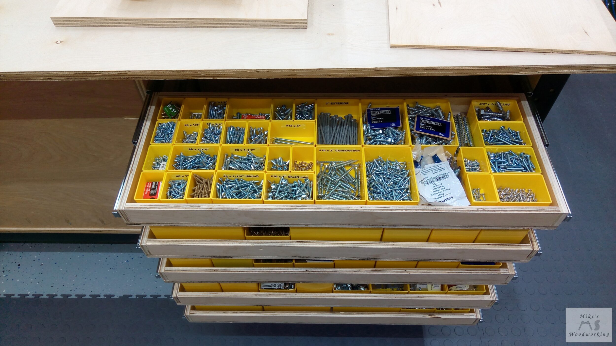
The bulk of the 60” shop stand’s space was now accounted for. The planer section took up all of the space front to back. The sander, however, still left a 28” W x 23” H x 10” D section behind it. I immediately had a thought on a use for that space. My hardware drawer in the miter saw station was already at capacity. I liked the construction of the parts drawer, utilizing the Stanley parts bins and the design that enables them to lock into place. It was tedious work drilling all of these holes the first time, bit it would be worth it if it worked.
I gathered the measurements of all of the different-sized bins and how many I had. I went through every drawer in my workshop and I found a few more hiding in various places. Based on the numbers, I would still have a bit of room leftover for additional bins. This was looking promising. Again, the question was whether there were 10” drawer slides available...CabinetParts.com to the rescue. I found exactly what I wanted, once again. The 60” shop stand was now complete. Now onto the 36” one.
I needed to replace some of the drawers from the old workbench as I still wanted to store some of those items by the workbench. The ones on the back would be slightly less deep to ensure both sides would close properly and not hit each other. A total of 16 drawers, eight 18” deep and eight 16” deep, would give me PLENTY of storage space for the majority of items previously stored in comparably-sized drawers from the old workbench. I already moved the hose reel and air compressor out of the workbench, so I no longer had to account for them anymore.
For the top of the workbench, I was going away from the double-lamination of 3/4” plywood. In its place would be a single layer of 3/4” plywood with a layer of 3/4” MDF on top of that. The top of the MDF would be sealed with shellac to prevent any swelling from contact with liquids. The perimeter of the top would get 3/4” hardwood trim, much like the old workbench.
For the overall height, I opted for the 32” shop stand legs with adjustable leveling feet. Coupled with the top, the overall height of the workbench will be between 35”-36”. I decided to make this workbench completely stationary, unlike the current one. I checked in my Sketchup drawings, and there will be no issues rearranging anything in the workshop for garage Tetris when it arises.
The workbench design is complete. It’s now time to make this thing.
Get to Work!!!
With all of the designs out of the way, finally, next up was to order the parts for all of the shop stands and any drawer slides I would need. Given that a lot of the upper miter saw station drawers were not changing, those slides would be reused. I took inventory of all the slides I would have available once the old shop stands were disassembled, and it turned out most of what I needed was already in the shop. The biggest expense was going to be all of the heavy-duty slides, nine sets in all. On top of those, I’d need five sets 10” slides for the new hardware drawers and six more sets of 16” slides for drawers under the workbench.
The price tag for all of these slides was not cheap, but I didn’t really have any alternatives. The numerous sets of Rockler shop stand legs and stretchers was also going to be a sizable cost but, again, this was the design I was going for, so I had to live with the expenses incurred. However, given that I had this whole project in mind well before Christmas, I received a lot of Rockler gift cards from family. Coupled with another large gift card I still had from my birthday, this cut my overall cost almost in half.
My original plan was to complete the Rockler Table Saw & Router Cabinet first, but the 28” shop stand legs were taking too long to ship (back-ordered), so I opted to start on the workbench instead. The first thing I needed to do was move the old workbench out of the way. Since I was going to disassemble it in preparation for reuse, I removed all of the drawers before moving it and just set them aside on the floor. The smaller drawers weren’t being reused, so I left everything stored in them in place. The two large drawers, however, were another matter. Those were to be reused, almost in their entirety.
With the old workbench now a skeleton, I installed the casters and wheeled it out of the way in preparation for the new one. Since the new workbench was to be stationary, I removed the floor tiles from the area. Trying to set up leveling feet on those tiles is a real pain, so just removing them from the equation was the only option. Luckily, the footprint for the new workbench didn’t require cutting the full-size tiles. I simply remove 10 of them and I was done.

And Now It’s Time for a Breakdown...
With the stands in place, next up was to head on down to Lakeland and Hardwood Lumber & Millwork (HLM) for the plywood needed. With lumber prices skyrocketing everywhere, there was no way to get around paying more now than if I’d done this project a couple of years prior. Even with the higher overall prices, HLM still had much better pricing than Big Orange or Big Blue.
Combined with the recycled materials in the shop, this project would call for five sheets of 3/4” plywood, two sheets of 1/2” plywood, and two sheets of 1/4” plywood. I opted for imported birch plywood instead of Baltic birch this time around. I simply couldn’t justify the added costs, although the quality of Baltic birch is much better than the imported stuff.
With all of the new materials back in the shop, it was time to break things into more manageable pieces. Not all of the material purchased would be needed for the workbench, so those pieces were set aside until needed. With all but one full sheet of 3/4” plywood partially broken down (the one left was for the top of the new workbench), now was time to work on breaking down the old workbench.
While unscrewing the top from the cabinet frames, it occurred to me that when I sandwiched the two pieces of plywood together, I used screws to hold them in place instead of nails. The screw heads weren’t visible from underneath, so that could only mean one thing...they were underneath the laminate. Uh oh!!!
I was at a loss at this point. I had no way of remembering where I placed all of the screws. I knew I laid them out in a grid, but what if I had used a few extra screws outside of said grid? I took a break from the shop to think about things for a bit and then an idea came to me during lunch. What if I used a small rare-earth magnet to see if I could locate the screws? I grabbed one of the magnets we used on the refrigerator and went back into the shop. I placed the magnet on the top and started slowly sliding it along and it snapped right onto one of the screws. I continued from there in a straight line and found where the other screws were. This was going to work.

This was the magnet I used to locate all of the screws in the old workbench top.
I drew a circle around the magnet at each screw location across the entire top. I did find a few spots that had some additional screws that I wouldn’t have known about otherwise. I got out my awl and a hammer and made a punch in the center of each circle. I used a 3/8” drill bit to open a hole where one of the screws was and tried removing it with my drill. It came out with zero problems, so I continued along in the same fashion for the rest of the screws.

All of the screws located and successfully removed. You can see a couple that strayed from the grid layout I mentioned.
With the top finally removed from the base, the cabinets were next to disassemble. All of the cabinets were screwed to each other, so those screws were removed first. With all of them now separated, all that was left was to remove all of the pocket screws holding each cabinet together. I’m glad I didn’t use glue in the construction of these cabinets. Each piece was labeled and set aside. Now’s it’s time to start putting this thing together.

Workbench Version 3 broken down on the Rockler Workbench stands.
I Love it When a Plan...Constantly Changes
The first thing to assemble and install were the panels that would get screwed to the insides of the 60” shop stand legs. This would take up the empty space and allow a beefy surface to attach the heavy-duty drawer slides. The composition of these panels would consist of a piece of 1/2” plywood sandwiched between two pieces of 3/4” plywood.
The top of the old workbench was to be used to make three of these panels, only two of which would be used on this project. The 1/2” plywood wouldn’t be placed between the 3/4” pieces, for obvious reasons. The ugly laminate side would face outwards on the inner section of both shop stands. This would eliminate them being seen, not that it really matters as this is a shop project.
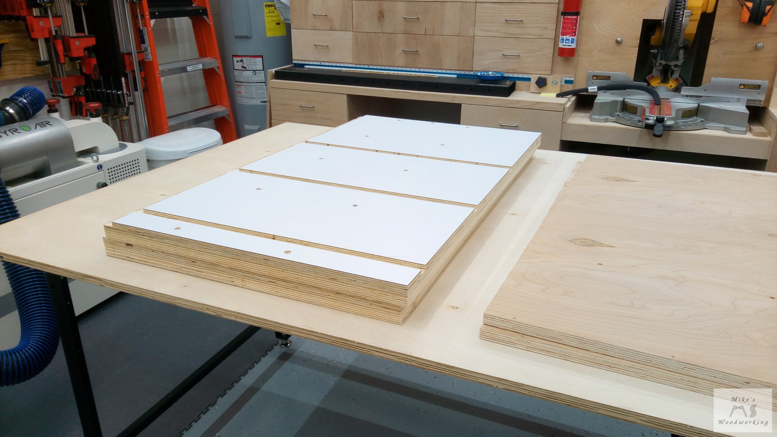
Here the old workbench top has been cut into the two pieces needed for the new workbench stands.
As part of my original plan, I would only be attaching a strip of 1/2” and 3/4” plywood to the outside 3/4” panel piece. The size and placement of the strips would coincide with the location of the drawer slides used in each shop stand. However, I changed my mind in the middle of the project and wanted a full-sized 1/2” and 3/4” panels throughout. With only two of such pieces accounted for in the plywood I bought, I had a bit of a problem.
I had plenty of scrap 3/4” plywood in the shop, but I didn’t want to go back out for just one sheet of 1/2” plywood. I started to scrounge around the shop for whatever scraps I could find. Luckily, I still had quite a bit hanging out on the tops of my two lumber racks and I was able cut enough pieces from those to fashion the panels I wanted.
With all of the pieces of the panels cut to size, they were all screwed together (no glue on this project) and set into place. It was a tight fit, so a bit of fine adjustment was needed by trimming off small amounts on the table saw. Once the fit was acceptable, the panels were screwed into place with 1-1/4” screws through the outside of the four legs.
Next up was to cut the bottom panel to size. I’ve learned through many past troublesome projects not to cut all of my parts based on measurements in plans or drawings. It is always best to reference such measurements from the project itself. My plans had the bottom to be cut at a length of 55-3/4”. The actual size needed turned out to be a full 1” shorter. For some reason, the 60” stretchers, when attached to the shop stand legs, don’t make a full 60” shop stand. All of the other stretchers are as advertised in their dimensions (terrible failure on the part of Rockler). This 1” difference was going to mean slight alterations to the locations of the divider panels. Thankfully, this would not cause problems with the execution of my original design.
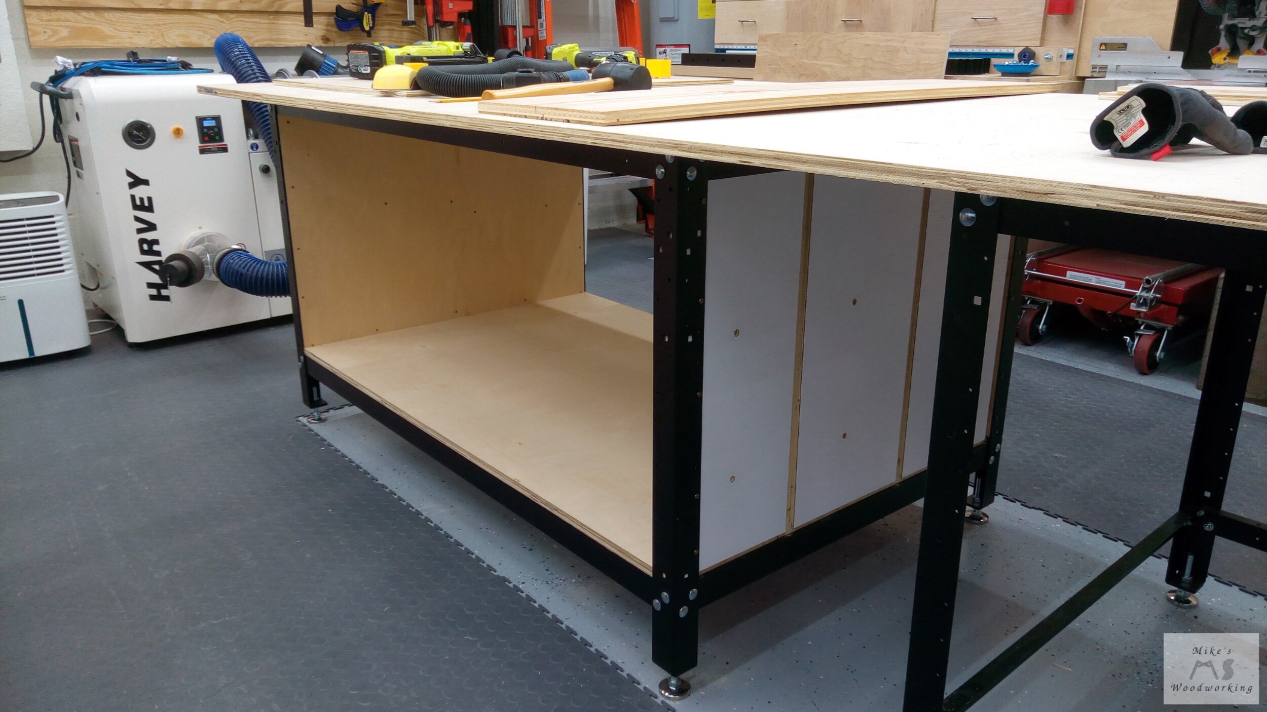

With the bottom panel set in place (no screws holding it down), it was time to cut the two divider panels to size. While they were both the same height, their lengths would be different. The divider for the planer would span the full 36” depth of the shop stand, while the one for the belt sander was 10” shorter. They were attached to the bottom by means of a number of pocket screws. The panels’ placements, while true to my original plans, led to them being closer together. The gap between them was slated to have a smaller filler piece put in place, but because of the smaller gap that is now out of the question.

Here are the two dividers in place (gotta love those out of order build images).
Now was time to cut the backs to size and secure them in place. Again, measurements were taken and the corresponding pieces cut. Pocket screws would be used again to secure the backs in place. The pocket screws for the planer back panel were left exposed on the outside, and this was intentional. With the angle of the pocket screws, having them on the inside would mean there wouldn’t be a lot of material for them to grab onto when screwed in place. While not entirely desirable to have them showing, it was necessary to maximize strength. Again, it’s a shop project, so it’s not THAT important to me.


With the backs now installed, the fronts of the dividers could still flex a bit, and with the weights involved with the planer and sander, coupled with the hefty drawer slides, these panels needed to be secured in place more firmly. I opted to attach some plywood stretchers to cover the span from the left side panel across both dividers. This provided a solid foundation for both tools. This was yet another thing that wasn’t a part of my original plan. It pays to have scraps around and the ability to make changes on the fly.

Again, more out of order picture-taking here (I’m working on it…).
This Flippin’ Thing Better Work
Now that the dividers were firmly secured in place, I decided to mount the heavy-duty drawer slides next. Their placement was already calculated based on my Sketchup drawing (one of the few times using the drawing measurements worked). With the length and overall weight of these slides and their eventual payload, I put a screw in almost every single available hole when attaching them to the workbench panels. There is no way that these things are going to come loose and fall down.
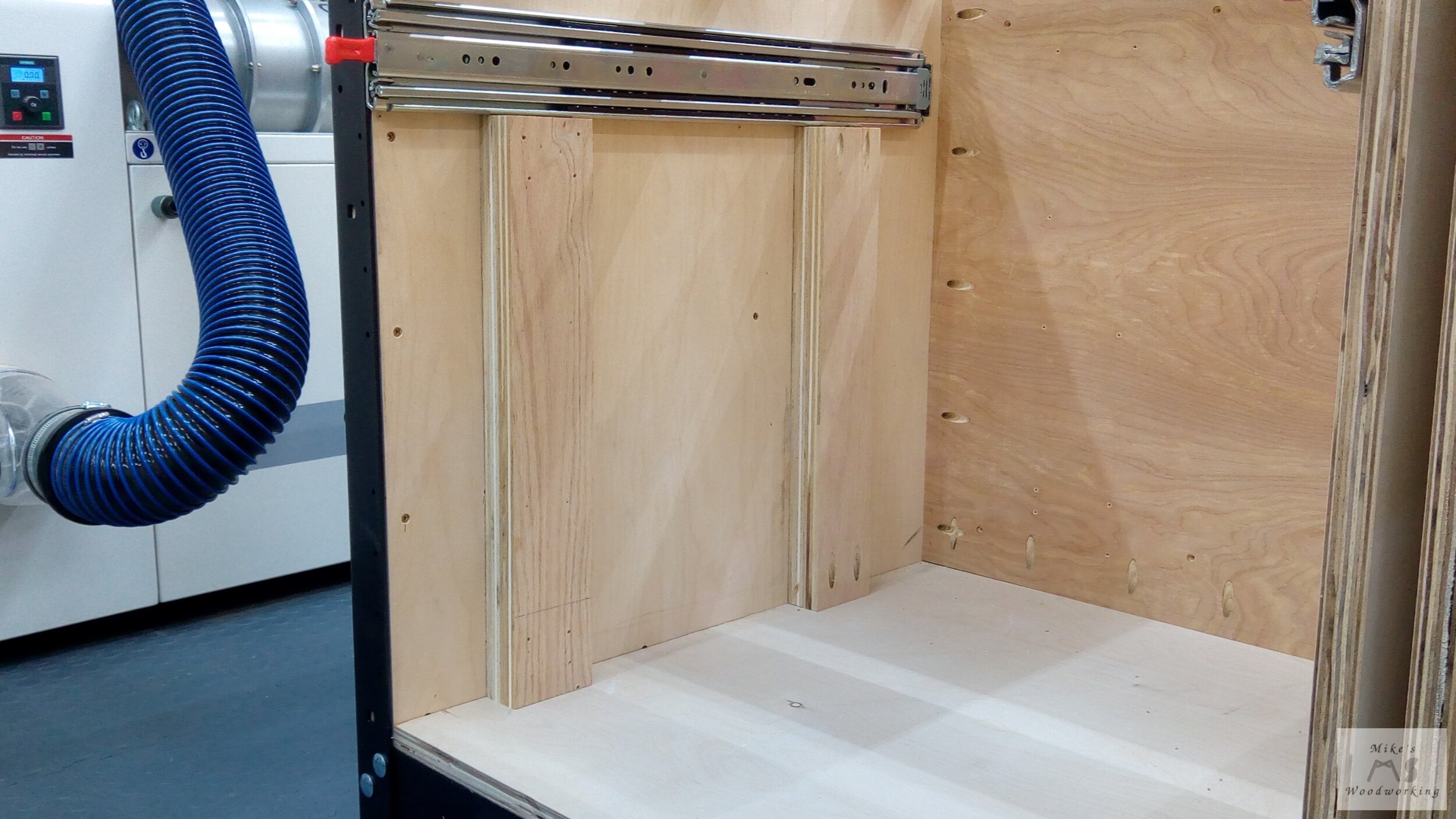
These double-thick spacers worked perfectly to hold these extra-heavy slides in place while screwing them in place.
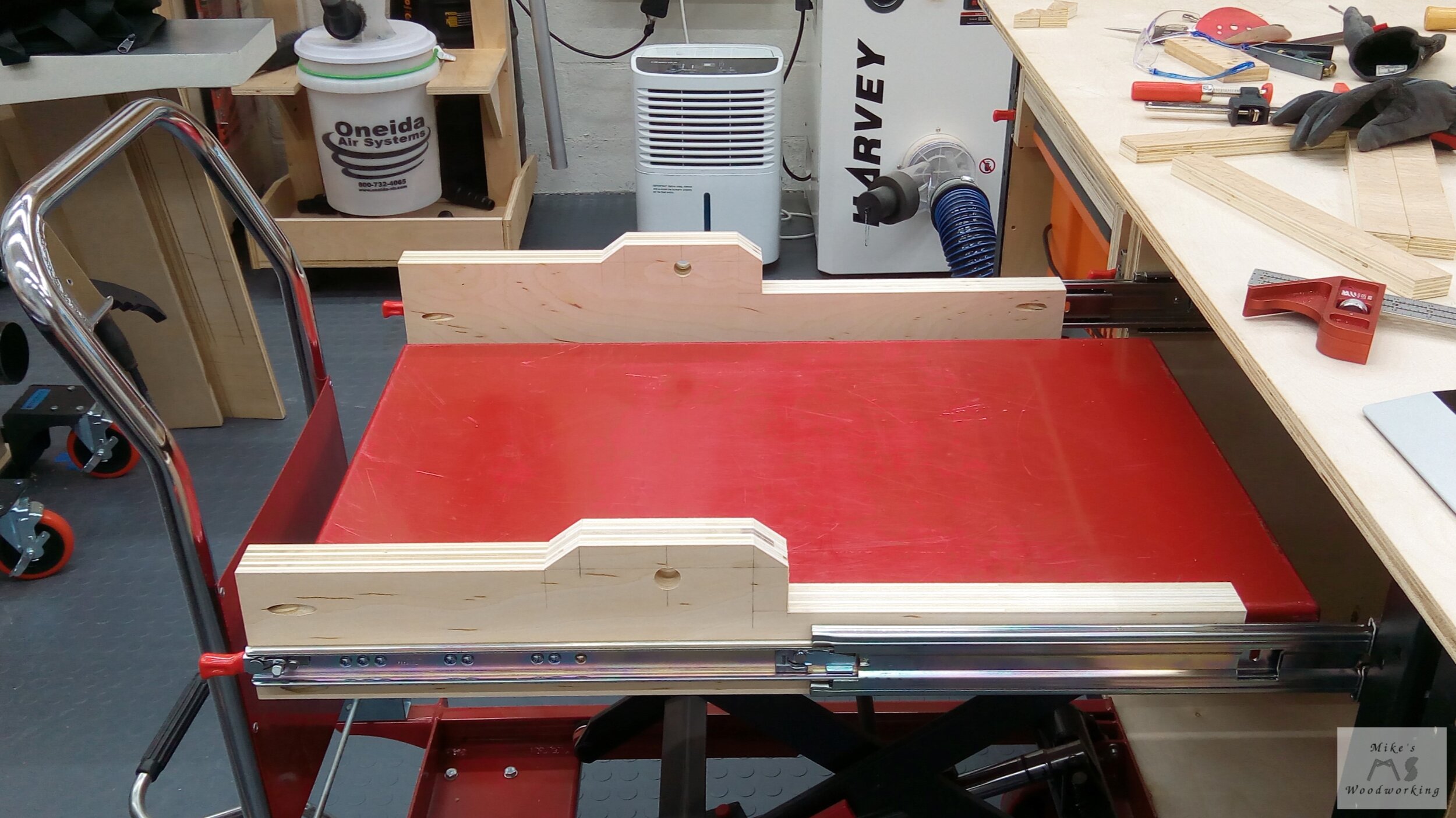
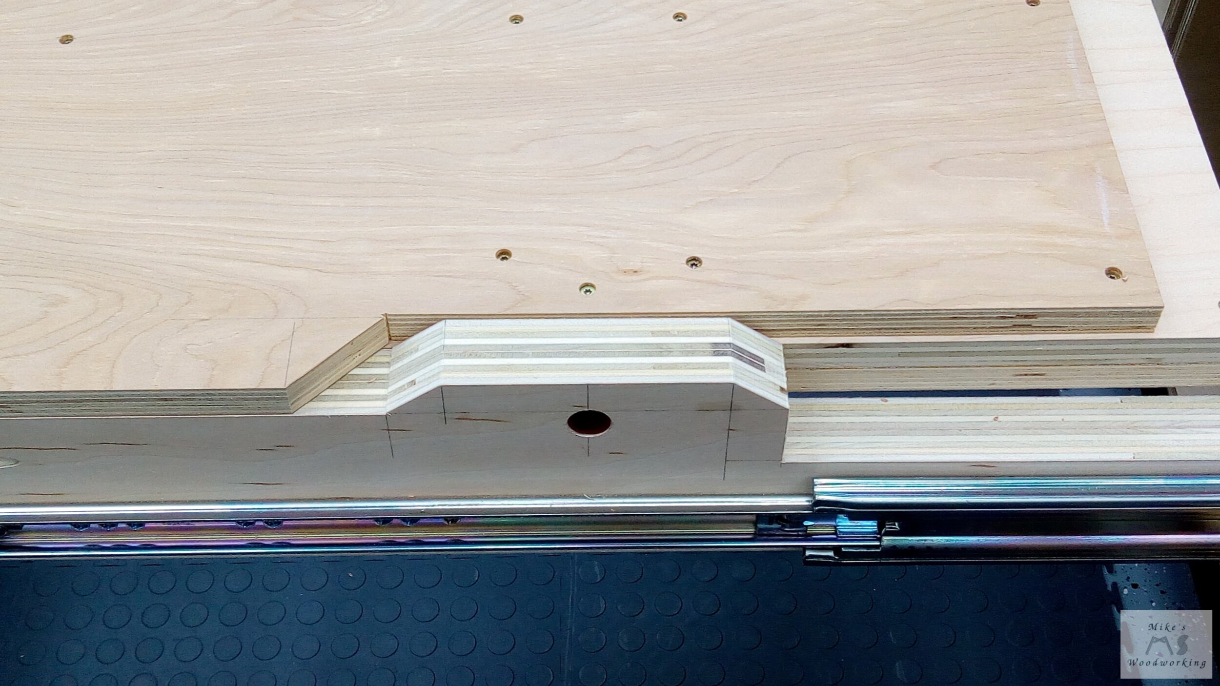
Next up was the sides of the drawers that would have the flip-top mechanism. I glued together four pairs of plywood pieces all cut to the same length and left them to marinate overnight. The next day I carefully made all of my marks for the layout of the flip-top pieces. I’m glad I double-checked my measurements because I almost screwed up the set for the belt sander. Always remember, measure 37 times and cut once. All of the cuts were made on the band saw, given the awkward shapes involved. With all of the cuts made, I clamped each set of drawer sides together and drilled the holes for the metal pipe, guaranteeing no chance of misalignment later.


Attaching the flip-top drawer sides to the slides was very straight-forward. I utilized the same set of spacers I used when attaching the slides to the workbench. To make my life a little easier, I used some double-sided tape to hold the slides in place so that I could attach the first few screws. Just like before, I put a screw into almost every hole available on the drawer sides to give me the most strength possible. With that out of the way, I tested out the slides and they worked flawlessly. They extend out the exact distance as planned, and the latches keep the slides locked into place in both the open and closed position.


In my eyes, the hard part is done at this point. All that was left now were the platforms that will encase the 3/4” steel pipe being used as the axle. Layout was a breeze, again mostly referencing Sketchup. I also looked back at Drew’s plans a couple of times just to make sure I had all of my cuts in the correct proportions, based on my platforms’ dimensions.
Getting the platforms into place called, once again, for my good friend the lift cart. With it holding the bottom section of the platform in place, I could easily slide the pipe into place and then screw the top together. I lowered the cart and tested the rotation of the platform and it worked nearly perfectly. The only problem was the pipe wanted to work its way out after a few rotations. The remedy this, I simply drilled a hole through the platform and put a single screw in place. The pipe was still free to rotate, but could no longer creep its way out like before.


I performed the same operation on the other platform and the drawers were finished. Their operation was smooth and there was no binding at all. I installed and secured both the planer and the belt sander with bolts and screws, respectively. Based on the position of the planer and its weight distribution, its center of mass was almost right over the pipe, making it very easy to flip. The belt sander was not as wide and because of where I positioned it on the platform, its center of mass is forward of the pipe, making it a little more difficult to flip. The belt sander isn’t anywhere near as heavy as the planer, so it’s not a huge deal.


My now old flip-top tool cart utilized some sash locks to secure the tools into place and prevent movement while in use. I couldn’t find a good location to place the sash locks on the new drawers, so I’m simply implementing a squeeze clamp to hold the tools in place. This seems to work just fine, so I might just go this route in the future instead of my other thought of installing barrel bolts.

With the weight of both tools, there is absolutely zero deflection of the drawer slides when fully extended and they are rock solid. The locking feature works perfectly and the slides operate very smoothly. One of the benefits of having the belt sander in its new position will be the working height. The top sits at just over 44” off the floor, compared to almost 48” before. This makes it much more comfortable for me, given my height.

I did notice one small problem when it comes to the sander in its closed position. My original plan of having a drawer underneath the sander to hold all of the sanding belts and spindles is no longer feasible. I completely neglected to take into account the metal shaft that runs the belt and spindles. It sticks out way too far and makes having a drawer under the sander impossible. The planer still has the space under it, but I decided to forgo the whole concept of added drawers under either of these tools entirely. For the time being, I’ll simply store all of the parts for each tool under them in the open area available. I may decide to make a removable tray to house said items in the future.
The most difficult part of the workbench is finished. The 60” shop stand is nearly complete, minus the hardware drawers and the doors in front of the planer and sander. The doors will now be full-height to take up the space left vacant by the abandoned drawers. Next up is the 36” shop stand.
Well, that was the plan at first. Then something else decided to stick its head in where it didn’t belong...a little something called shingles. I was derailed for almost two weeks while recovering from shingles. You can read more about what I was dealing with here.
Rinse & Repeat...For the Most Part
After conquering my bout with shingles, I could get back to the task at hand. The basic construction for the 36” shop stand was the same as the 60” one, with the bottom being about half the size and no back panels. The lone divider panel was placed as close to the center of the opening as possible with the aid of some spacers, and stretchers were added to keep the divider firmly in place.


I next cut all of the pieces for the drawers. The height for all of the drawers is the same, so this was easy enough. For the drawer fronts/backs, that was simply a matter of taking the opening, subtracting 1”, then using two pieces of scrap material and placing that next to a stop block on my crosscut sled. This guaranteed a perfect fit for the drawers. There were eight drawers on each side of the divider, so each set was done at the same time to avoid any mistakes. The length of the sides was then cut for each set of 18” and 16” drawers. I held off on the assembly for the moment.

I opted to install all of the drawer slides next. They all needed to be at the same positions for all 16 drawers, but I went ahead and offset one side by 3/4” to ensure the screws in the divider panel didn’t hit each other. I very easily could have left all the slides at the same height and used different screw holes on the slides, but that thought never entered my mind at the time.
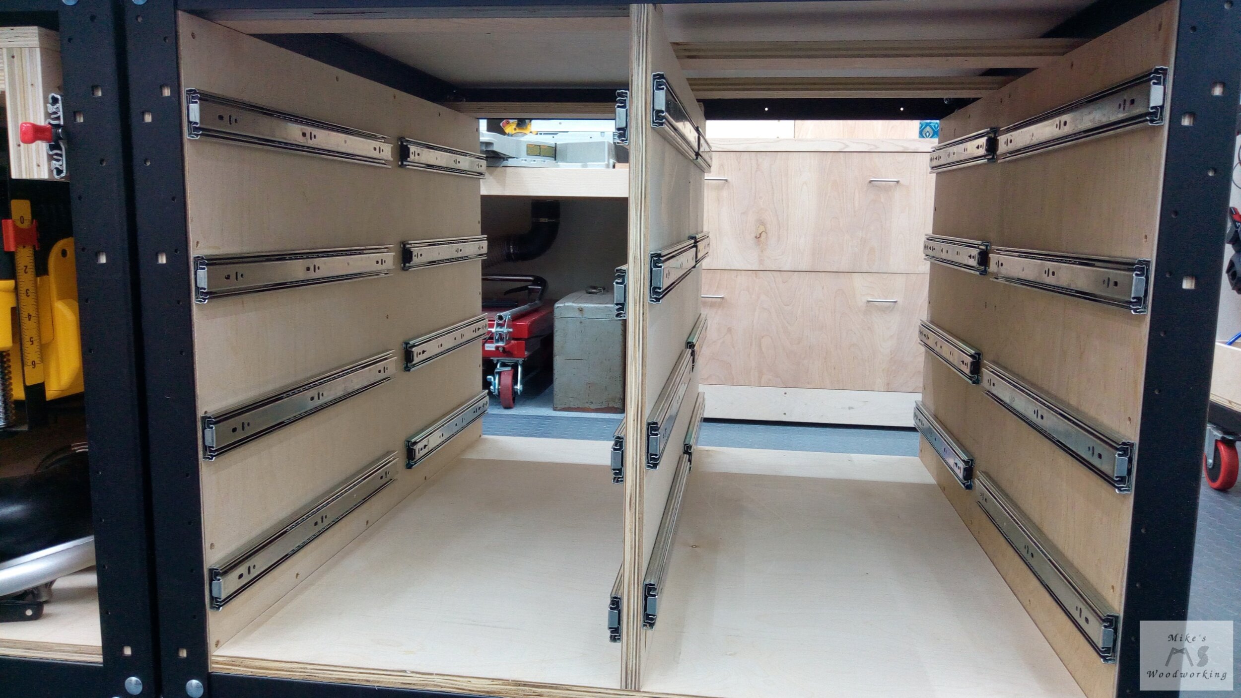
Here you can see that I spaced one set of slides off by 3/4” from the others on the divider.
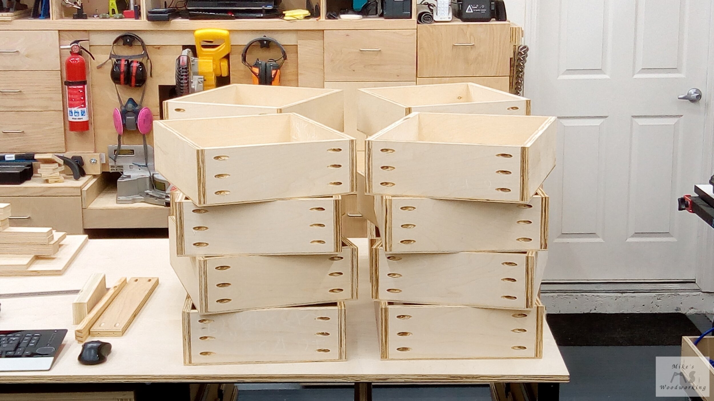
Assembling the drawers was a trivial matter. I used simple pocket hole construction on all of the drawers and that came together rather quickly. With all of the drawers build, I double-checked the measurements and set out to cut all of the drawer bottoms. Again, using my crosscut sled and panel-cutting sled made for quick and repeatable cuts. I went with 1/4” plywood for the bottoms as these drawers wouldn’t have a lot of heavy objects in them. A small bead of glue and some brad nails was all that was needed to secure the bottoms in place. Before locking the bottoms in place, I made sure to get the drawer boxes square with the bottoms. Most were dead on, but a couple needed a diagonal clamping to get them square.
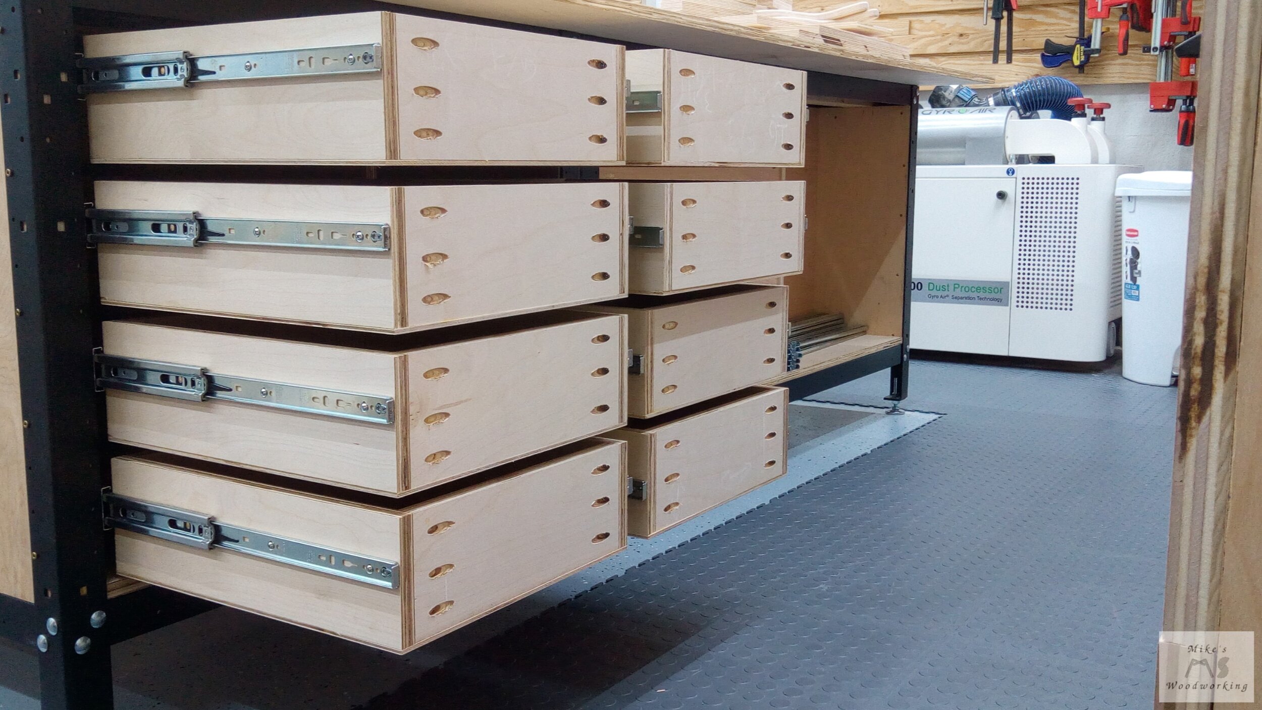
Installing the drawers went very quickly. Using the same spacers for each drawer made for little to no guesswork throughout the entire process. On some of the 16” drawers, you can definitely tell which ones had the newer sets of slides as they didn’t come out quite as far as the older ones.


Holy Holes, Batman!!!
The most tedious portion of this project was left for last, and those were the hardware drawers. Given that I was going with the same design as my larger hardware drawer located in my miter saw station, I had A LOT of holes to drill...and I mean A LOT!!!
Between the large drawer and the two smaller inset ones, the current hardware drawer had 285 holes drilled. The new drawers were going to require 425 holes between the five of them. The original was too large to make use of my drill press, so I drilled all of those with a cordless drill and a forstner bit. With these new smaller drawers, I was going all-in on the drill press this time.
I laid out my grids on each piece and made a small punch with my awl and a hammer at each intersection. This would give the forstner bit a place to center itself without having to stop the drill between holes to line up the bit. I initially clamped a fence into place to guarantee a straight line for each row of holes, but I found that the bit did a good enough job of centering on the plywood to not need the fence at all. There was enough slop built into the design and layout of these holes to make up for any slight variance in drilling.


All of the holes were at a depth of about 1/4” in 1/2” plywood. For the first hardware drawer, I used a 3/4” forstner bit, but the fit wasn’t quite right with the larger Stanley bins. My old hardware drawer had 13/16” holes, but I no longer had that size bit since I gave that set to Habitat for Humanity after I bought a nicer set of Fisch forstner bits. The new set didn’t have 13/16”, so I had to make a trip down to Rockler to get that one specific bit. It was a long trip just for that, but it was still quicker than ordering it online and waiting for it to be shipped (no local hardware stores had a bit in that specific size).

That a lot of freakin’ holes, man!!! Now do the same thing FOUR more times…dick.
The four subsequent drawers had 13/16” holes and the fit was perfect. Using the drill press made the whole process go much quicker than by hand like I had done a couple of years prior. With the 1/2” plywood sides and fronts/backs simply glued and nailed together, all five hardware drawers went together quickly.

Before installing the 10” drawer slides, I made sure to double-check my spacing multiple times. With the slides installed, next up were the drawers themselves. These went in without much issue. When they were all in place, I was worried that they might suffer from binding, given that they are much wider than they are deep. I had that problem with a large wide and shallow drawer in my first workbench many years prior, but that was more likely due to poor drawer construction. These slid in and out smoothly and effortlessly. All that was left was to transfer all of the Stanley bins from the old to the new. The results were exactly as envisioned.


Let’s Face It...You Suck at Faces
The least favorite part of drawer installation was pretty much all that remained on this project. There were a total 16 drawer faces that needed to be installed, and drawer faces and I have a rather bad history. With the exception of the soon-to-be disassembled drill press cart, every set of drawer faces I’ve ever installed have been absolutely terrible. Now, with that being said, all of those past projects suffered from some poor craftsmanship on my part, so I can only blame myself for how things turned out. This time around, I made sure all aspects of my build were as square as possibly before installing them.
I was going for a continuous grain look for both sets of drawers, so I made sure to carefully lay out everything before making my cuts. I intended to go with a 1/8” reveal all around the drawer faces, using a homemade shim. Given the problems I’ve had in the past with said shim, I opted to use the blades from my Woodpeckers combination squares as the shims. They are 3/32” thick, just 1/32” less than I would prefer, but I felt it was worth having a dead-on thickness using these instead of the wooden shim which was not a true 1/8” all the way across.
Before I got started with the drawer faces, I noticed that some of the drawers themselves looked a little cockeyed. I went through each and every drawer and made minor adjustments until each one was parallel to the one below. With that now looking much straighter, I set off on the drawer faces.
I double-checked the measurement of the bottom left drawer face, and made my first cut. I took my time in getting this one lined up perfectly before securing it in place with four screws from the inside. I continued my way up until I got all four left side drawer faces installed. I repeated the same process on the four right side drawer faces. When I was done, I was ecstatic with the results. I had a consistent gap all the way around and everything looked perfect.

The continuous grain is hard to make out in this picture.
With much more confidence, I went ahead and repeated everything I had just done for the rear set of drawers. And just as with the front set, the rear drawers came out perfect!!! These were the best sets of drawers I’d ever made...and it only took me over three years to do it.

The continuous grain can be seen a bit clearer here.
A Sinking Feeling
The only thing left at this point, other than cabinet hardware, were the two sets of doors for the planer and belt sander. With the lower drawers out of the picture, these doors would be the full height of the opening. Like the drawer faces I’d just finished, I was going with a continuous grain look for the doors.
Before cutting the doors to size, I needed to measure the opening. I checked the right side of the planer opening and then the left side. The left was about 1/16” more than the right. How was THAT possible? I checked the sander and it had the same problem, only in reverse. Both of the outer measurements, closest to the shop stand legs matched, but the ones in the middle were both off by 1/16”.
I took a closer look and I noticed that the dividers in the middle of the 60” stretchers weren’t flush with the top stretcher. Because of the weight of both tools and the drawer slides, the bottom stretcher was deflecting a bit. This was a huge problem, to say the least. The rear bottom stretcher appeared to be fine and showed little to no deflection.
I needed a way to prop up the middle of that front bottom stretcher before I could begin working on the doors. I had plenty of heavy-duty leveling feet in the shop, but how could I install them on that stretcher? There are a set of five holes evenly spaced on the front of those stretchers. I thought, maybe, I could attach two leveling feet to a piece of plywood that spanned the middle three holes, and use them to straighten the stretcher. I did just that and started cranking on the leveling feet. The gap began to shrink and soon the opening was completely square again. My idea had actually worked. I used two leveling feet, but I probably only needed one (more on that later).
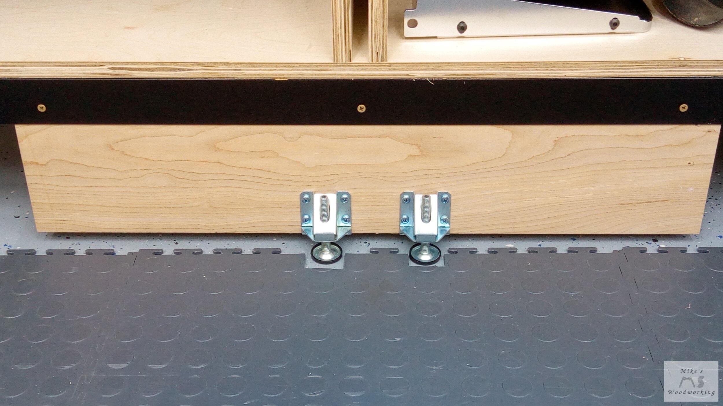
I had to cut notches in this floor tile to make room for the leveling feet.
With that mini-crisis averted, it was time to get these doors finished. Doors are one of the few things that have not been a problem for me in the shop. These four would be no different. Because of the use of drawers behind the doors, I had to get some zero-protrusion hinges that cleared the doors out of the way for full access to the drawer inside. These hinges used the same Rockler jigs I already had on hand, so installation was a breeze. The top hinge on both sets of doors would not be located near the top of the door due to the drawer slides being there. It was no problem moving them further down, about 1/3 of the way from the top.
A notch needed to be cut out on each door to make room for the locking lever on each drawer slide. This was easy enough to cut out using the band saw. I locked each door into place, and used the adjustment screws on each hinge to level everything and make for a consistent gap. The end results were nearly as perfect as the drawer faces.
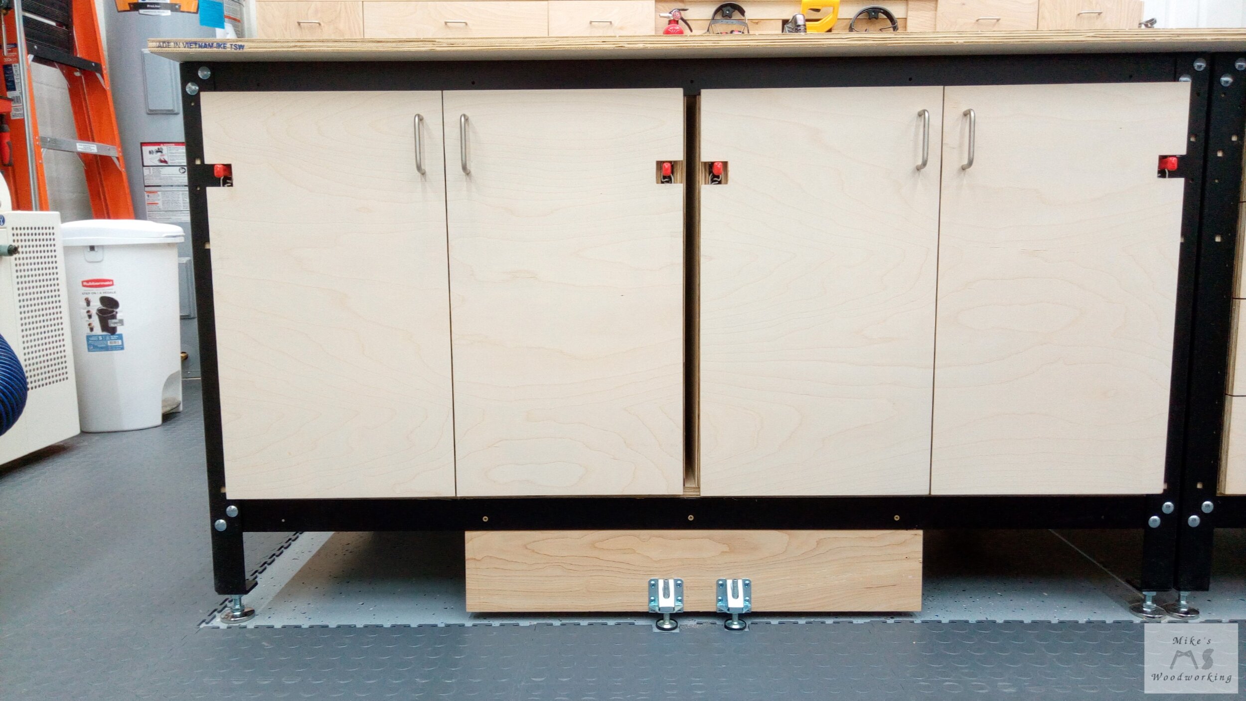


With the addition of the drawer and door pulls the Rockler workbench was complete, save for the top. I cut the plywood top to the size I required and secured it in place from underneath. For the MDF top, I cut it 1/2” over-sized in both directions, secured it to the plywood from underneath, and then used a flush-trim router bit to get it to match the plywood perfectly. After two coats of shellac, it looked great (well, sorta…my brush work needs some SERIOUS work).


You can also see that I changed the old leveling feet setup and switched it out for just one and moved it to face the inside versus the outside. Because of the way the old setup was installed, and the shape of the rails themselves, the leveling feet were causing the stretcher to bend outwards a bit. Having two feet on the front was a bit excessive anyway. Although I don’t think it was necessary, I installed a leveling foot on the rear stretcher as well.
Another means of support I added well after the fact was a leveling foot near the center of the bottom panels on both workbench stands. I installed one each on the workbench stands to prevent any kind of sagging of the plywood over time. It wasn’t easy to screw into place after the fact, but I got it done.
That pretty much does it for the Rockler Workbench build, minus the hardwood trim. I’ll install all of the trim after the other two projects in this series are both completed. I’ll also amend this article and add finished photos once the trim is installed.
I loaded up the drawers with all of the things from the old workbench and I still had some room to spare. The old flip-top tool cart was taken apart and its parts will be used for the remaining two Rockler projects in this large build.
The next project in this series will be the Rockler Table Saw & Router Cabinet.
***UPDATE: June 2023***
It’s been a solid two years since I built the Rockler Workbench. I think I spend more time at this particular station in my workshop than any other, and for good reason. It is in the center of nearly all of my major tools/workstations.
Not a single project goes by where I am not utilizing the workbench. From stock prep to organizing parts after cutting them at the table saw, this station is in the middle of everything.
After using it continuously for a couple of years, I think I can now make a fair assessment.
There are a total of 16 drawers on the right side of the bench. These hold anything from measuring and marking tools to squeeze clamps to everything else in between. Some of the drawers are still holding a lot of miscellaneous junk and I’m fine with that. All of this stuff was kind of strewn about in the shop’s previous iteration, so having things more contained is a definite plus.
The five hardware drawers have performed exactly as I expected they would. Not much has changed here other than going through certain bits of hardware and replacing others. A couple of the drawers don’t close perfectly, mostly due to my own inaccuracies when installing the drawer slides. It’s nothing that causes any issues while at the bench.
Probably the biggest surprise with the bench was the continued functionality of the flip-top tool compartments housing my Ridgid oscillating belt sander and DeWalt planer. The main goal was to get these tools off of the floor and the workbench allowed me to accomplish that with ease.
I still use a simple quick-grip clamp to hold both tools in place while in use, and this has shown to be more than sufficient. I far and away get more use out of the planer than the sander, but that is not too surprising at this stage in my woodworking journey.
As far as storage of the various parts that go with each of these tools, I have them all sitting on the base of the cabinet under the tools. I thought about making some kind of trays for this, but I didn’t see much point in that.
The heavy-duty locking drawer slides have performed flawlessly every time, and the flipping mechanism works great as well. The sander is still a little awkward to spin around because the center of mass is not over the pivot point, but it’s not too unwieldy compared to the planer. Thankfully, the planer is more or less dead-nuts centered on the pivot, making flipping it a breeze. Don’t get me wrong, that thing still weighs a ton, but it’s nothing I can’t manage (at least currently).
The feet I installed to support the long center braces are still holding up just fine and serve their purpose well.
This brings me to the top itself. My original plan was to install removable hardwood trim all around the top to protect the edges…that never happened. I don’t think it is really needed at this point, at least not on the long edges. The short edges are another story.
Firstly, I had to move both sets of combination wrenches I had hanging on a French cleat on the one side of the bench. I was constantly bumping into them and knocking them onto the floor. And considering I no longer have the rubber floor tiles to dampen the sound anymore, those wrenches hitting the concrete are LOUD!!! They are now hanging on the French cleat wall above my dust processor, well out of the way.
After all the time using this workbench, probably my biggest complaint with it is I have no means of clamping anything to the table along the short edges. Because the stands are 8’ long, a sheet of plywood offers no lip on those sides. I knew this going in and didn’t figure this would be a problem as I have the two long edges to use for clamping. However, there have been some occasions where having the ability to clamp on both sides of the corner of the bench would have been handy. Having the hardwood edging might afford me enough of an edge to allow clamping.
To be honest, I simply don’t feel like going through the trouble of prepping and installing the hardwood edging. The edges of the MDF and plywood have held up remarkably well thus far.
Shortly after I built this workbench, Rockler came out with a new set of adjustable shop stands which took into account the need for clamping all the way around the bench. While this would eliminate my clamping problems on the short edges, the sizes of the compartments in the now smaller stands would mean I might not be able to house both of my power tools. It’s a bit of a double-edged sword.
With that being said, I think I would rather forego the expanded clamping edges for the larger space to house my two tools.
Lastly, I was a bit worried about the durability of the MDF top. I finished it with shellac coated with polycrylic. I didn’t use wax-free shellac, so the polycrylic will easily scratch and flake off if I drag certain things across the top. There’s a chance I might still sand off all of the finish and start from scratch again with something different.
Despite my best efforts, the top is not dead flat, as I expected would be the case. Without the use of a torsion box, it was going to be very difficult to get a perfectly flat top with only a layer of plywood and MDF. With that being said, the top is still flat enough for most applications and I see no need to do anything further with it.
I’ve scratched up the top quite a bit in places when cutting poster board for making gift boxes, and there’s the marked-up section where I was laying out the batteries and chargers for Lumber Cart 3.0.
I’ve often wondered if I made the right choice in not installing t-track in a section of the workbench top. Looking back after a couple of years of use, I think the jury is still out on that. While there were a few times the t-track would have come in handy for work-holding, I found other ways to work around this issue with the aid of my moxon vise, among other things.
In the grand scheme of things, I’d have to say the workbench is working out very well and there isn’t much else I’d change about it. There is the small chance I might lower the workbench slightly so that it is in line with the height of my table saw, but it isn’t strictly necessary. Considering I’ve not really made any changes to this project, I’d have to still call it a huge win.
We’ll see what happens over the next couple of years.